Part III. Services / Chapter 22. Basic Networking | ||||
|---|---|---|---|---|
 | Part III. Services | 22.2. IPv6—The Next Generation Internet |  | |
Part III. Services / Chapter 22. Basic Networking | ||||
|---|---|---|---|---|
| Part III. Services | 22.2. IPv6—The Next Generation Internet | | |
Table of Contents
Abstract
Linux, really a child of the Internet, offers all the necessary networking tools and features for integration into all types of network structures. The customary Linux protocol, TCP/IP, has various services and special features, which are discussed here. Network access using a network card, modem, or other device can be configured with YaST. Manual configuration is also possible. Only the fundamental mechanisms and the relevant network configuration files are discussed in this chapter.
Linux and other Unix operating systems use the TCP/IP protocol. It is not a single network protocol, but a family of network protocols that offer various services. The protocols listed in Table 22.1, “Several Protocols in the TCP/IP Protocol Family” are provided for the purpose of exchanging data between two machines via TCP/IP. Networks combined by TCP/IP, comprising a worldwide network are also referred to, in their entirety, as “the Internet.”
RFC stands for Request for Comments. RFCs are documents that describe various Internet protocols and implementation procedures for the operating system and its applications. The RFC documents describe the setup of Internet protocols. To expand your knowledge about any of the protocols, refer to the appropriate RFC documents. They are available online at http://www.ietf.org/rfc.html.
Table 22.1. Several Protocols in the TCP/IP Protocol Family
Protocol | Description |
|---|---|
Transmission Control Protocol: A connection-oriented secure protocol. The data to transmit is first sent by the application as a stream of data then converted by the operating system to the appropriate format. The data arrives at the respective application on the destination host in the original data stream format in which it was initially sent. TCP determines whether any data has been lost during the transmission and that there is no mix-up. TCP is implemented wherever the data sequence matters. | |
User Datagram Protocol: A connectionless, insecure protocol. The data to transmit is sent in the form of packets generated by the application. The order in which the data arrives at the recipient is not guaranteed and data loss is a possibility. UDP is suitable for record-oriented applications. It features a smaller latency period than TCP. | |
Internet Control Message Protocol: Essentially, this is not a protocol for the end user, but a special control protocol that issues error reports and can control the behavior of machines participating in TCP/IP data transfer. In addition, it provides a special echo mode that can be viewed using the program ping. | |
Internet Group Management Protocol: This protocol controls machine behavior when implementing IP multicast. |
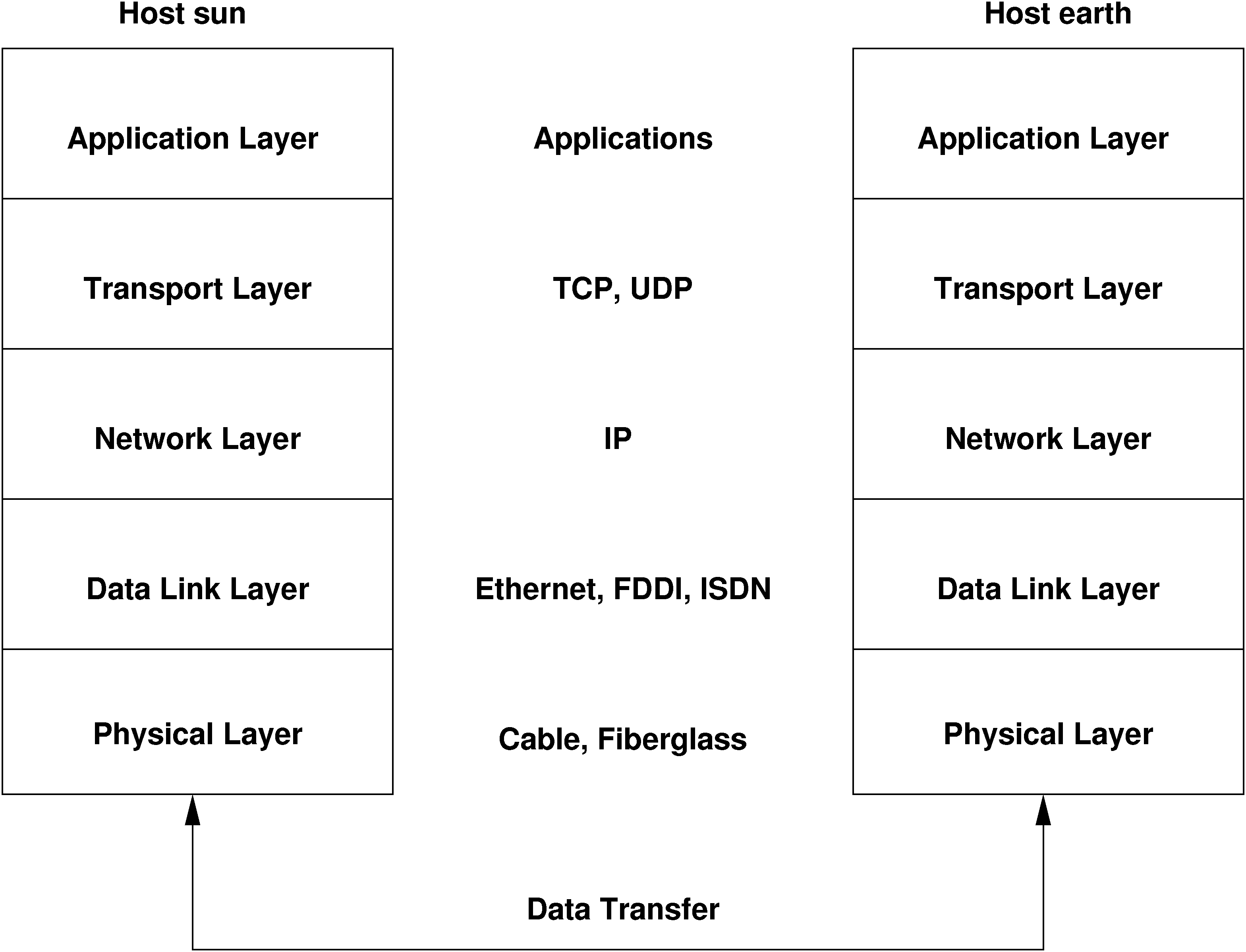
As shown in Figure 22.1, “Simplified Layer Model for TCP/IP”, data exchange takes place in different layers. The actual network layer is the insecure data transfer via IP (Internet protocol). On top of IP, TCP (transmission control protocol) guarantees, to a certain extent, security of the data transfer. The IP layer is supported by the underlying hardware-dependent protocol, such as ethernet.
The diagram provides one or two examples for each layer. The layers are ordered according to abstraction levels. The lowest layer is very close to the hardware. The uppermost layer, however, is almost a complete abstraction from the hardware. Every layer has its own special function. The special functions of each layer are mostly implicit in their description. The data link and physical layers represent the physical network used (such as ethernet).
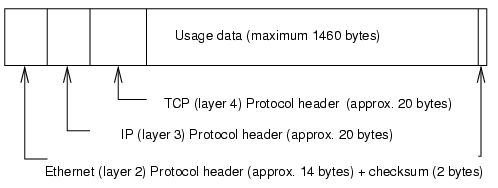
Almost all hardware protocols work on a packet-oriented basis. The data to transmit is packaged in packets, because it cannot be sent all at once. The maximum size of a TCP/IP packet is approximately 64 KB. Packets are normally quite a bit smaller, because the network hardware can be a limiting factor. The maximum size of a data packet on an ethernet is about fifteen hundred bytes. The size of a TCP/IP packet is limited to this amount when the data is sent over an ethernet. If more data is transferred, more data packets need to be sent by the operating system.
For the layers to serve their designated functions, additional information regarding each layer must be saved in the data packet. This takes place in the header of the packet. Every layer attaches a small block of data, called the protocol header, to the front of each emerging packet. A sample TCP/IP data packet traveling over an ethernet cable is illustrated in Figure 22.2, “TCP/IP Ethernet Packet”. The proof sum is located at the end of the packet, not at the beginning. This simplifies things for the network hardware.
When an application sends data over the network, the data passes through each layer, all implemented in the Linux kernel except the physical layer. Each layer is responsible for preparing the data so it can be passed to the next layer. The lowest layer is ultimately responsible for sending the data. The entire procedure is reversed when data is received. Like the layers of an onion, in each layer the protocol headers are removed from the transported data. Finally, the transport layer is responsible for making the data available for use by the applications at the destination. In this manner, one layer only communicates with the layer directly above or below it. For applications, it is irrelevant whether data is transmitted via a 100 MBit/s FDDI network or via a 56-kbit/s modem line. Likewise, it is irrelevant for the data line which kind of data is transmitted, as long as packets are in the correct format.
The discussion in this section is limited to IPv4 networks. For information about IPv6 protocol, the successor to IPv4, refer to Section 22.2, “IPv6—The Next Generation Internet”.
Every computer on the Internet has a unique 32-bit address. These 32 bits (or 4 bytes) are normally written as illustrated in the second row in Example 22.1, “Writing IP Addresses”.
Example 22.1. Writing IP Addresses
IP Address (binary):  11000000 10101000 00000000 00010100
IP Address (decimal):      192.     168.       0.      20
In decimal form, the four bytes are written in the decimal number system, separated by periods. The IP address is assigned to a host or a network interface. It cannot be used anywhere else in the world. There are certainly exceptions to this rule, but these play a minimal role in the following passages.
The ethernet card itself has its own unique address, the MAC, or media access control address. It is 48 bits, internationally unique, and is programmed into the hardware by the network card vendor. There is, however, an unfortunate disadvantage of vendor-assigned addresses—MAC addresses do not make up a hierarchical system, but are instead more or less randomly distributed. Therefore, they cannot be used for addressing remote machines. The MAC address still plays an important role in communication between hosts in a local network and is the main component of the protocol header of the data link layer.
The points in IP addresses indicate the hierarchical system. Until the 1990s, IP addresses were strictly categorized in classes. However, this system has proven too inflexible so was discontinued. Now, classless routing (CIDR, classless interdomain routing) is used.
Netmasks were conceived for the purpose of informing the host with the IP address 192.168.0.1 of the location of the host with the IP address 192.168.0.20. To put it simply, the netmask on a host with an IP address defines what is internal and what is external. Hosts located internally (“in the same subnetwork”) respond directly. Hosts located externally (“not in the same subnetwork”) only respond via a gateway or router. Because every network interface can receive its own IP address, it can get quite complicated.
Before a network packet is sent, the following runs on the computer: the IP address is linked to the netmask via a logical AND and the address of the sending host is connected to the netmask via the logical AND. If there are several network interfaces available, normally all possible sender addresses are verified. The results of the AND links are compared. If there are no discrepancies in this comparison, the destination, or receiving host, is located in the same subnetwork. Otherwise, it must be accessed via a gateway. The more “1” bits are located in the netmask, the fewer hosts can be accessed directly and the more hosts can be reached via a gateway. Several examples are illustrated in Example 22.2, “Linking IP Addresses to the Netmask”.
Example 22.2. Linking IP Addresses to the Netmask
IP address (192.168.0.20):  11000000 10101000 00000000 00010100
Netmask   (255.255.255.0):  11111111 11111111 11111111 00000000
---------------------------------------------------------------
Result of the link:         11000000 10101000 00000000 00000000
In the decimal system:           192.     168.       0.       0

IP address (213.95.15.200): 11010101 10111111 00001111 11001000
Netmask    (255.255.255.0): 11111111 11111111 11111111 00000000
---------------------------------------------------------------
Result of the link:         11010101 10111111 00001111 00000000
In the decimal system:           213.      95.      15.       0
The netmasks appear, like IP addresses, in decimal form divided by periods. Because the netmask is also a 32-bit value, four number values are written next to each other. Which hosts are gateways and which address domains are accessible over which network interfaces must be configured.
To give another example: all machines connected with the same ethernet cable are usually located in the same subnetwork and are directly accessible. When the ethernet is divided by switches or bridges, these hosts can still be reached.
However, the economical ethernet is not suitable for covering larger
distances. You must transfer the IP packets to other hardware,
such as FDDI or ISDN. Devices for this transfer are called routers or
gateways. A Linux machine can carry out this task. The respective
option is referred to as ip_forwarding.
If a gateway has been configured, the IP packet is sent to the appropriate gateway. This then attempts to forward the packet in the same manner—from host to host—until it reaches the destination host or the packet's TTL (time to live) expires.
Table 22.2. Specific Addresses
Address Type | Description |
|---|---|
This is the netmask AND any address in the network, as shown
in Example 22.2, “Linking IP Addresses to the Netmask” under
| |
This basically says, “Access all hosts in this subnetwork.” To generate this, the netmask is inverted in binary form and linked to the base network address with a logical OR. The above example therefore results in 192.168.0.255. This address cannot be assigned to any hosts. | |
The address |
Because IP addresses must be unique all over the world, you cannot just select random addresses. There are three address domains to use to set up a private IP-based network. With these, you cannot set up any connections to the rest of the Internet, unless you apply certain tricks, because these addresses cannot be transmitted over the Internet. These address domains are specified in RFC 1597 and listed in Table 22.3, “Private IP Address Domains”.