Linux, really a child of the Internet, offers all the necessary
networking tools and features for integration into all types of
network structures. An introduction into the customary Linux
protocol, TCP/IP, follows. The various services and special features
of this protocol are discussed. Network access using a network card
can be configured with YaST. The central configuration files are
discussed and some of the most essential tools described.
Only the fundamental mechanisms and the relevant network
configuration files are discussed in this chapter.
The configuration of Internet access with PPP via modem, ISDN, or
other connection can be completed with YaST. It is described in the
User Guide.
Linux and other Unix operating systems use the TCP/IP protocol. It is not a single network protocol, but a family of network protocols that offer various services. TCP/IP was developed based on an application used for military purposes and was defined in its present form in an RFC in 1981. RFC stands for ``Request for Comments''. They are documents that describe various Internet protocols and implementation procedures for the operating system and its applications. Since then, the TCP/IP protocol has been refined, but the basic protocol has remained virtually unchanged.
Tip
The RFC documents describe the setup of Internet
protocols. To expand your knowledge about any of the protocols,
refer to the appropriate RFC document. They are available online at
http://www.ietf.org/rfc.html
The services listed in Table 13.1 are provided for the purpose of exchanging data between two Linux machines via TCP/IP. Networks combined by TCP/IP, comprising a world-wide network are also referred to, in their entirety, as ``the Internet''.
Almost all hardware protocols work on a packet-oriented basis. The data to transmit is packaged in ``bundles'', as it cannot be sent all at once. This is why TCP/IP only works with small data packets. The maximum size of a TCP/IP packet is approximately sixty-four kilobytes. The packets are normally quite a bit smaller, as the network software can be a limiting factor. The maximum size of a data packet on an ethernet is about fifteen hundred bytes. The size of a TCP/IP packet is limited to this amount when the data is sent over an ethernet. If more data is transferred, more data packets need to be sent by the operating system.
IP (Internet Protocol) is where the insecure data transfer takes place. TCP (Transmission Control Protocol), to a certain extent, is simply the upper layer for the IP platform serving to guarantee secure data transfer. The IP layer itself is, in turn, supported by the bottom layer, the hardware-dependent protocol, such as ethernet. Professionals refer to this structure as the ``layer model''. See Figure 13.1.
The diagram provides one or two examples for each layer. As you can see, the layers are ordered according to ``degrees of abstraction''. The lowest layer is very close to the hardware. The uppermost layer, however, is almost a complete abstraction from the hardware. Every layer has its own special function.
The special functions of each layer are already implicit in their description. For example, the network used (e.g., ethernet) is depicted by the bit transfer and security layers.
For every layer to serve its designated function, additional information regarding each layer must be saved in the data packet. This takes place in the header of the packet. Every layer attaches a small block of data, called the protocol header, to the front of each emerging packet. A sample TCP/IP data packet traveling over an ethernet cable is illustrated in Figure 13.2.
The proof sum is located at the end of the packet, not at the beginning. This simplifies things for the network hardware. The largest amount of usage data possible in one packet is 1460 bytes in an ethernet network.
When an application sends data over the network, the data passes through each layer, all implemented in the Linux kernel except layer 1 (network card). Each layer is responsible for preparing the data so it can be passed to the next layer below. The lowest layer is ultimately responsible for sending the data.
The entire procedure is reversed when data is received. Like the layers of an onion, in each layer the protocol headers are removed from the usage data. Finally, layer 4 is responsible for making the data available for use by the applications at the destination.
In this manner, one layer only communicates with the layer directly above or below it. For applications, it is irrelevant whether data is transmitted via a 100 MBit/s FDDI network or via a 56-kbit/s modem line. Likewise, it is irrelevant for the data line which kind of data is being transmitted, as long as packets are in the correct format.
Note
The discussion in the following sections is limited to IPv4
networks. For information about IPv6 protocol, the
successor to IPv4, refer to Section 13.
Every computer on the Internet has a unique 32-bit address. These 32 bits (or 4 bytes) are normally written as illustrated in the second row in Table 13.2.
| tex2html_deferred |
The ethernet card itself has its own unique address, the MAC, or media access control address. It is 48 bits long, internationally unique, and is programmed into the hardware by the network card vendor. There is, however, an unfortunate disadvantage of vendor-assigned addresses -- MAC addresses do not make up a hierarchical system, but are instead more or less randomly distributed. Therefore, they cannot be used for addressing remote machines. The MAC address still plays an important role in communication between hosts in a local network and is the main component of the protocol header of layer 2.
The points in IP addresses indicate the hierarchical system. Until the 1990s, IP addresses were strictly categorized in classes. However, this system has proven too inflexible so was discontinued. Now, ``classless routing'' (or CIDR, Classless Inter Domain Routing) is used.
Netmasks were conceived for the purpose of informing the host with the IP address 192.168.0 .20 of the location of the host with the IP address 192.168.0 .1. To put it simply, the netmask on a host with an IP address defines what is ``internal'' and what is ``external''. Hosts located ``internally'' (professionals say, ``in the same subnetwork'') respond directly. Hosts located ``externally'' (``not in the same subnetwork'') only respond via a gateway or router. Because every network interface can receive its own IP address, it can get quite complicated.
Before a network packet is sent, the following runs on the computer: the IP address is linked to the netmask via a logical AND and the address of the sending host is likewise connected to the netmask via the logical AND. If there are several network interfaces available, normally all possible sender addresses are verified. The results of the AND links will be compared. If there are no discrepancies in this comparison, the destination, or receiving host, is located in the same subnetwork. Otherwise, it must be accessed via a gateway. The more ``1'' bits are located in the netmask, the fewer hosts can be accessed directly and the more hosts can be reached via a gateway. Several examples are illustrated in Table 13.3.
The netmasks appear, like IP addresses, in decimal form divided by periods. Because the netmask is also a 32-bit value, four number values are written next to each other. Which hosts are gateways or which address domains are accessible over which network interfaces must be entered in the user configurations.
To give another example: all machines connected with the same ethernet cable are usually located in the same subnetwork and are directly accessible. When the ethernet is divided by switches or bridges, these hosts can still be reached.
However, the economical ethernet is not suitable for covering larger distances. You must transfer the IP packets to another hardware (e.g. , FDDI or ISDN). Devices for this transfer are called routers or gateways. A Linux machine can carry out this task. The respective option is referred to as ip_forwarding.
If a gateway has been configured, the IP packet is sent to the appropriate gateway. This then attempts to forward the packet in the same manner -- from host to host -- until it reaches the destination host or the packet's TTL (time to live) has expired.
| Specific Addresses | |
| Address Type | Description |
|---|---|
| Base network address | This is the netmask AND any address in the network, as shown in Table 13.3 under Result. This address cannot be assigned to any hosts. |
| Broadcast address | This basically says, ``Access all hosts in this subnetwork.'' To generate this, the netmask is inverted in binary form and linked to the base network address with a logical OR. The above example therefore results in 192.168.0.255. This address cannot be assigned to any hosts. |
| Local host | The address 127.0.0.1 is strictly assigned to the ``loopback device'' on each host. A connection can be set up to your own machine with this address. |
As IP addresses must be unique all over the world, you cannot just come up with your own random addresses. There are three address domains to use to set up a private IP-based network. With these, you cannot set up any connections to the rest of the Internet, unless you apply certain tricks, because these addresses cannot be transmitted over the Internet. These address domains are specified in RFC 1597 and listed in Table 13.5.
| Private IP Address Domains | |
| Network/Netmask | Domain |
|---|---|
| 10.0.0.0/255.0.0.0 | 10.x.x.x |
| 172.16.0.0/255.240.0.0 | 172.16.x.x - 172.31.x.x |
| 192.168.0.0/255.255.0.0 | 192.168.x.x |
DNS serves to alleviate the burden of having to remember IP addresses: DNS assists in assigning an IP address to one or more names and assigning a name to an IP address. In Linux, this conversion is usually carried out by a special type of software known as bind. The machine that takes care of this conversion is called a name server.
The names make up a hierarchical system in which each name component is divided by dots. The name hierarchy is, however, independent of the IP address hierarchy described above.
Consider a complete name, such as laurent.suse.de, written in the format hostname.domain. A full name, referred to by experts as a ``fully qualified domain name'', or FQDN for short, consists of a host name and a domain name (suse.de). The latter also includes the top level domain or TLD (de).
TLD assignment has become, for historical reasons, quite confusing. Traditionally, three-letter domain names are used in the USA. In the rest of the world, the two-letter ISO national codes are the standard. In addition to that, in the year 2000 new multiletter TLDs have been introduced that represent certain spheres of activity (for example, .info, .name, .museum).
In the early days of the Internet (before 1990), the file /etc/hosts was used to store the names of all the machines represented over the Internet. This quickly proved to be impractical in the face of the rapidly growing number of computers connected to the Internet. For this reason, a decentralized database was developed to store the host names in a widely distributed manner. This database, similar to the name server, does not have the data pertaining to all hosts in the Internet readily available, but can dispatch requests to other name servers.
The top of the hierarchy is occupied by ``root name servers''. These root name servers manage the top level domains and are run by the Network Information Center, or NIC. Each root name server knows about the name servers responsible for a given top level domain. More information about top level domain NICs is available at http://www.internic.net.
DNS can do more than just resolve host names. The name server also knows which host is receiving e-mails for an entire domain -- the mail exchanger (MX).
For your machine to resolve an IP address, it must know about at least one name server and its IP address. Easily specify such a name server with the help of YaST. If you have a modem dial-up connection, you may not need to configure a name server manually at all. The dial-up protocol provides the name server address as the connection is made. The configuration of name server access with SuSE Linux is described in 13.
The protocol whois is closely related to DNS. With this program, quickly find out who is responsible for any given domain.
Due to the emergence of the WWW (World Wide Web), the Internet has experienced explosive growth with an increasing number of computers communicating via TCP/IP in the last ten years. Since Tim Berners-Lee at CERN (http://public.web.cern.ch/) invented the WWW in 1990, the number of Internet hosts has grown from a few thousand to about 100 million.
As mentioned, an IP address consists of ``only'' 32 bits. Also, quite a few IP addresses are lost -- they cannot be used due to the way in which networks are organized. The number of addresses available in your subnet is the number of bits squared minus two. A subnetwork has, for example, two, six, or fourteen addresses available. To connect 128 hosts to the Internet, for instance, you need a subnetwork with 256 IP addresses, from which only 254 are usable, because two IP addresses are needed for the structure of the subnetwork itself: the broadcast and the base network address.
Under the current IPv4 protocol, DHCP or NAT (network address translation) are the typical mechanisms used to circumvent the potential address shortage. Combined with the convention to keep private and public address spaces separate, these methods can certainly mitigate the shortage. The problem with them lies in their configuration, which is quite a chore to set up and a burden to maintain. To set up a host in an IPv4 network, you need to find out about quite a number of address items, such as the host's own IP address, the subnetmask, the gateway address, and maybe a name server address. In fact, all these items need to be known, meaning they cannot be derived from somewhere else.
With IPv6, both the address shortage and the complicated configuration should be a thing of the past. The following sections tell more about the improvements and benefits brought by IPv6 and about the transition from the old protocol to the new one.
The most important and most visible improvement brought by the new protocol is the enormous expansion of the available address space. An IPv6 address is made up of 128 bit values instead of the traditional 32 bits. This provides for as many as several quadrillion IP addresses.
However, IPv6 addresses are not only different from their predecessors with regard to their length. They also have a different internal structure that may contain more specific information about the systems and the networks to which they belong. More details about this are found in Section 13.
The following is a list of some other advantages of the new protocol:
As mentioned, the current IP protocol is lacking in two important aspects: on the one hand, there is an increasing shortage of IP addresses; on the other hand, configuring the network and maintaining the routing tables is becoming a more and more complex and burdensome task. IPv6 solves the first problem by expanding the address space to 128 bits. The second one is countered by introducing a hierarchical address structure, combined with sophisticated techniques to allocate network addresses, as well as multihoming (the ability to allocate several addresses to one device, thus giving access to several networks).
When dealing with IPv6, it is useful to know about three different types of addresses:
An IPv6 address is made up of eight four-digit fields, each of them representing sixteen bits, written in hexadecimal notation. They are also separated by colons (:). Any leading zero bytes within a given field may be dropped, but zeros within the field or at its end may not. Another convention is that more than four consecutive zero bytes may be collapsed into a double colon. However, only one such :: is allowed per address. This kind of shorthand notation is shown in Output 16, where all three lines represent the same address.
Each part of an IPv6 address has a defined function. The first bytes form the prefix and specify the type of address. The center part is the network portion of the address, but it may be unused. The end of the address forms the host part. With IPv6, the netmask is defined by indicating the length of the prefix after a slash at the end of the address. An address as shown in Output 17 contains the information that the first 64 bits form the network part of the address and the last 64 form its host part. In other words, the 64 means that the netmask is filled with 64 1-bit values from the left. Just like with IPv4, the IP address is ANDed with the values from the netmask to determine whether the host is located in the same subnetwork or in another one.
IPv6 knows about several predefined types of prefixes, some of which are shown in Table 13.6.
| Various IPv6 Prefixes | |
| Prefix (hex) | Definition |
|---|---|
| * 00 | IPv4 addresses and IPv4 over IPv6 compatibility addresses. These are used to maintain compatibility with IPv4. Their use still requires a router able to translate IPv6 packets into IPv4 packets. Several special addresses (such as that for the loopback device) have this prefix as well. |
| 2 or 3 as the first digit | Aggregatable global unicast addresses. As is the case with IPv4, an interface can be assigned to form part of a certain subnetwork. Currently, there are the following address spaces: 2001::/16 (production quality address space), 2002::/16 (6to4 address space), and 3ffe::/16 (6bone.net). |
| fe80::/10 | Link-local addresses. Addresses with this prefix are not supposed to be routed and should therefore only be reachable from within the same subnetwork. |
| fec0::/10 | Site-local addresses. These may be routed, but only within the network of the organization to which they belong. In effect, they are the IPv6 equivalent of the current private network address space (e.g., 10.x.x.x). |
| ff | These are multicast addresses.
|
A unicast address consists of three basic components:
On top of this basic structure, IPv6 distinguishes between five different types of unicast addresses:
As a completely new feature introduced with IPv6, each network interface normally gets several IP addresses, with the advantage that several networks can be accessed through the same interface. One of these networks can be configured in completely automatic fashion, using the MAC and a known prefix, with the result that all hosts on the local network can be reached as soon as IPv6 is enabled (using the link-local address). With the MAC forming part of it, any IP address used in the world is unique. The only variable parts of the address are those specifying the site topology and the public topology, depending on the actual network where the host is currently operating.
For a host to go back and forth between different networks, it needs at least two addresses. One of them, the home address, not only contains the interface ID but also an identifier of the home network to which it normally belongs (and the corresponding prefix). The home address is a static address and, as such, it does not normally change. Still, all packets destined to the mobile host can be delivered to it, no matter whether it operates in the home network or somewhere outside. This is made possible by the completely new features introduced with IPv6, such as stateless autoconfiguration and neighbor discovery. In addition to its home address, a mobile host gets one or more further addresses that belong to the foreign networks where it is roaming. These are called care-of addresses. The home network has a facility that forwards any packets destined to the host when it is roaming outside. In an IPv6 environment, this task is performed by the home agent, which takes all packets destined to the home address and relays them through a tunnel. On the other hand, those packets destined to the care-of address are directly transferred to the mobile host without any special detours.
It is unlikely that all hosts connected to the Internet will switch from IPv4 to IPv6 overnight. A rather more likely scenario is that both protocols will need to coexist for some time to come. The coexistence on one system is guaranteed where there is a dual stack implementation of both protocols. That still leaves the question how an IPv6 enabled host is supposed to communicate with an IPv4 host and how IPv6 packets should be transported by the current networks, which are predominantly IPv4 based.
The first problem can be solved with compatibility addresses (see Section 13), the second one by introducing a number of different tunneling techniques. IPv6 hosts that are more or less isolated in the (worldwide) IPv4 network can communicate through a specially wrapped channel -- IPv6 packets are encapsulated as IPv4 packets to move them across an IPv4 network. Such a connection between two IPv4 hosts is called a tunnel. To achieve this, packets must include the IPv6 destination address (or the corresponding prefix) as well as the IPv4 address of the remote host at the receiving end of the tunnel. A basic tunnel can be configured manually according to an agreement between the hosts' administrators. This is also called static tunneling.
However, the configuration and maintenance of static tunnels is often too labor-intensive to use them for daily communication needs. Therefore, IPv6 provides for three different methods of dynamic tunneling:
Note
[The 6bone initiative]In the heart of the ``old-time'' Internet,
there is already a globally distributed network of IPv6 subnets that are
connected through tunnels. This is the 6bone network (www.6bone.net), an
IPv6 test environment that may be used by programmers and Internet providers
who want to develop and offer IPv6 based services in order to gain the
experience necessary to implement the new protocol. More information can be
found on the project's Internet site.
The above overview does not cover the topic of IPv6 comprehensively. For a more in-depth look at the new protocol, refer to the following online documentation and books:
Currently TCP/IP is the standard network protocol. All modern operating systems can communicate via TCP/IP. Nevertheless, Linux also supports other network protocols, such as IPX (previously) implemented by Novell Netware or Appletalk used by Macintosh machines. Only the integration of a Linux machine into a TCP/IP network is discussed here. To integrate ``exotic'' arcnet, token rings, or FDDI network cards, refer to the kernel sources documentation at /usr/src/linux/Documentation. For information about network configuration changes made in SuSE Linux version 8.0, read the file /usr/share/doc/packages/sysconfig/README.
The machine has to have a supported network card. Normally, the network card will already be recognized during installation and the appropriate driver loaded. See if your card has been integrated properly by entering the command ifstatus eth0. The output should show the status of the network device eth0.
If the kernel support for the network card is
implemented as a module, as is usually the case with the SuSE
kernel, the name of the module must be entered as an alias
in /etc/modules.conf. For example, for the first ethernet
card:
alias eth0 tulip
This will occur automatically if the driver support is started in
the linuxrc during the first installation. Otherwise,
start it via YaST at a later time.
If you are using a hotplug network card (e.g. , PCMCIA or USB), the drivers are autodetected when the card is plugged in. No configuration is necessary. Find more information in 7.
To configure the network card with YaST, start the Control Center and select ` Network - Devices' ->` Network Card Configuration'. With ` Add', configure a new network card. With ` Delete', remove it from the configuration. With ` Edit', modify the network card configuration.
Activate the check box ` Hardware' to modify the hardware data for an already configured network card with ` Edit'. This opens the dialog for changing the settings of the network card, shown in Figure 13.3.
Normally, the correct driver for your network card is configured during installation and is activated. Therefore, manual hardware parameter settings are only needed if multiple network cards are used or if the network hardware is not automatically recognized. In this case, select ` Add' to specify a new driver module.
In this dialog, set the network card type and, for an ISA card, the interrupt to implement and the IO address. For some network drivers, also specify special parameters, such as the interface to use or whether it uses an RJ-45 or a BNC connection. For this, refer to the driver module documentation. To use PCMCIA or USB activate the respective check boxes.
After entering the hardware parameters, configure additional network interface data. Select ` Interface' in the dialog ` Network Base Configuration' to activate the network card and assign it an IP address. Select the card number then click ` Edit'. A new dialog will appear in which to specify the IP address and other IP network data. Find information about assigning addresses to your own network in 13 and Table 13.5. Otherwise, enter the address assigned by your network administrator in the designated fields.
Configure a name server under ` Host Name and Name Server' so the name resolution functions as described in 13. Via ` Routing', set up the routing. Select ` Configuration for Experts' to make advanced settings.
If you are using wireless lan network cards, activate the check box ` Wireless Device'. In the dialog window, set the most important options, like operation mode, network names, and the key for encrypted data transfer.
With that, the network configuration is complete. YaST starts SuSEconfig and transfers the settings to the corresponding files (see 13). For the changes to take effect, the relevant programs must be reconfigured and the required daemons must be restarted. This is done by entering the command rcnetwork restart.
Hotplug network cards, like PCMCIA or USB devices, are managed in a somewhat special way. Normal network cards are fixed components assigned a permanent device name, such as eth0. By contrast, PCMCIA cards are assigned a free device name dynamically on an as-needed basis. To avoid conflicts with fixed network cards, hotplug and PCMCIA services are loaded after the network has been started.
PCMCIA-related configuration and start scripts are located in the directory /etc/sysconfig/pcmcia. The scripts will be executed as soon as cardmgr, the PCMCIA Device Manager, detects a newly inserted PCMCIA card -- which is why PCMCIA services do not need to be started before the network during boot.
To configure IPv6, you will not normally need to make any changes on the individual workstations. However, the IPv6 support will have to be loaded. Do this most easily by entering the command modprobe ipv6.
Because of the autoconfiguration concept of IPv6, the network card is assigned an address in the ``link-local'' network. Normally, no routing table management takes place on a workstation. The network routers can be queried by the workstation, using the ``router advertisement protocol'', for what prefix and gateways should be implemented. The radvd program can be used to set up an IPv6 router. This program informs the workstations which prefix to use for the IPv6 addresses and which routers. Alternatively, use zebra for automatic configuration of both addresses and routing.
Consult the manual page of ifup (man ifup) to get information about how to set up various types of tunnels using the /etc/sysconfig/network files.
Manual configuration of the network software should always be the last alternative. We recommend using YaST.
All network interfaces are set up with the script /sbin/ifup. To halt the interface, use ifdown. To check its status, use ifstatus.
If you only have normal, built-in network cards, configure the interfaces by name. With the commands ifup eth0, ifstatus eth0, and ifdown eth0, start, check, or stop the interface eth0. The respective configuration files are stored in /etc/sysconfig/network/ifcfg-eth0. eth0 is the name of the interface and the name of the configuration.
The network can alternatively be configured in relation to the hardware address (MAC address) of a network card. In this case, a configuration file ifcfg-<hardware address without colon> is used. Use lowercase characters in the hardware address, as displayed by the command ip link (ifconfig shows uppercase letters). If ifup finds a configuration file matching the hardware address, a possibly existing file ifcfg-eth0 will be ignored.
Things are a little more complicated with hotplug network cards. If you do not use one of those cards, skip the following sections and continue reading 13.
Hotplug network cards are assigned the interface name arbitrarily, so the configuration for one of those cards cannot be stored under the name of the interface. Instead, a name is used that contains the kind of hardware and the connection point. In the following, this name is referred to as the hardware description. ifup has to be called with two arguments -- the hardware description and the current interface name. ifup will then determine the configuration that best fits the hardware description.
For example, a laptop with two PCMCIA slots, a PCMCIA ethernet network card and a built-in network card configured as interface eth0 is configured in the following way: The built-in network card is in slot 0 and its hardware description is eth-pcmcia-0. The program cardmgr or the hotplug network script runs the command ifup eth-pcmcia-0 eth1 and ifup searches in /etc/sysconfig/network/ for a file ifcfg-eth-pcmcia-0. If there is no such file, it looks for ifcfg-eth-pcmcia, ifcfg-pcmcia-0, ifcfg-pcmcia, ifcfg-eth1 and ifcfg-eth. The first of these files found by ifup is used for the configuration. To generate a network configuration valid for all PCMCIA network cards in all slots, the configuration file must be named ifcfg-pcmcia.
This file would then be used for the ethernet card in slot 0 (eth-pcmcia-0) as well as for a token ring card in slot 1 (tr-pcmcia-1). A configuration depending on the hardware address is treated with higher priority.
YaST lists the configurations for hotplug cards and accordingly writes the settings to ifcfg-eth-pcmcia-<number>. To use such a configuration file for all slots, a link ifcfg-eth-pcmcia points to this file. Keep this in mind if you sometimes configure the network with and sometimes without YaST.
This section provides an overview of the network configuration files and explains their purpose and the format used.
The configuration files contain the IP address (BOOTPROTO=static, IPADDR=10.10.11.214) or the direction to use DHCP (BOOTPROTO=dhcp). The IP address may also include the netmask (IPADDR=10.10.11.214/16) or the netmask can be specified separately (NETMASK=255.255.0.0). Refer to ifup for the complete list of variables.
In addition, all the variables in the files dhcp, wireless, and config can be used in the ifcfg-* files, if a general setting is only to be used for one interface. By using the variables POST_UP_SCRIPT and PRE_DOWN_SCRIPT, individual scripts can be run after starting or before stopping the interface.
The file config contains general settings for the behavior of ifup, ifdown, and ifstatus. dhcp contains settings for DHCP and wireless for wireless lan cards. The variables in all three configuration files are commented and can also be used in ifcfg-* files, where they are treated with higher priority.
| Parameters for /etc/host.conf | |
| Specifies in which order the services are accessed for the name resolution. Available arguments are (separated by blank spaces or commas): | |
| hosts: Searches the /etc/hosts file | |
| bind: Accesses a name server | |
| nis: Via NIS | |
| multi on/off | Defines if a host entered in /etc/hosts can have multiple IP addresses. |
| nospoof on alert on/off |
These parameters influence the name server spoofing, but, apart from that, do not exert any influence on the network configuration. |
| trim <domainname> | The specified domain name is separated from the host name after host name resolution (as long as the host name includes the domain name). This option is useful if only names from the local domain are in the /etc/hosts file, but should still be recognized with the attached domain names. |
An example for /etc/host.conf is shown in File 30.
In the /etc/nsswitch.conf file, the order of certain data is defined. An example of nsswitch.conf is shown in File 31. Comments are preceeded by `#' signs. Here, for instance, the entry under ``database'' hosts means that a request is sent to /etc/hosts (files) via DNS (see 13).
The ``databases'' available over NSS are listed in Table 13.8. In addition, automount, bootparams, netmasks, and publickey are expected in the near future.
| Available Databases via /etc/nsswitch.conf | |
|
aliases |
Mail aliases implemented by sendmail(8). See also the man page for aliases. |
| ethers | Ethernet addresses. |
| group | For user groups, used by getgrent(3). See also the man page for group. |
| hosts | For host names and IP addresses, used by gethostbyname(3) and similar functions. |
| netgroup | Valid host and user lists in the network for the purpose of controlling access permissions. See also the man page for netgroup. |
| networks | Network names and addresses, used by getnetent(3). |
| passwd | User passwords, used by getpwent(3). See also the man page for passwd. |
| protocols | Network protocols, used by getprotoent(3). See also the man page for protocols. |
| rpc | ``Remote Procedure Call'' names and addresses, used by getrpcbyname(3) and similar functions. |
| services | Network services, used by getservent(3). |
| shadow | ``Shadow'' user passwords, used by getspnam(3). See also the man page for shadow. |
The configuration options for NSS databases are listed in Table 13.9.
| Configuration Options for NSS ``Databases'' | |
|
files |
directly access files, for example, to /etc/aliases. |
| db | access via a database. |
| nis | NIS, see also 13. |
| nisplus | |
| dns | Only usable by hosts and networks as an extension. |
| compat | Only usable by passwd, shadow, and group as an extension. |
| also | It is possible to trigger various reactions with certain lookup results. Details can be found in the man page for nsswitch.conf. |
| Caution |
If, for example, the caching for passwd is activated, it will usually take about fifteen seconds until a newly added user is recognized by the system. By restarting nscd, reduce this waiting period. |
An example of /etc/resolv.conf is shown in File 32.
Some services, like pppd (wvdial), ipppd (isdn), dhcp (dhcpcd and dhclient), pcmcia, and hotplug, modify the file /etc/resolv.conf. To do so, they rely on the script modify_resolvconf.
If the file /etc/resolv.conf has been temporarily modified by this script, it will contain a predefined comment giving information about the service by which it has been modified, about the location where the original file has been backed up, and hints on how to turn off the automatic modification mechanism.
If /etc/resolv.conf is modified several times, the file will include modifications in a nested form. These can be reverted in a clean way even if this reversal takes place in an order different from the order in which modifications where introduced. Services that may need this flexibility include isdn, pcmcia, and hotplug.
If it happens that a service was not terminated in a normal, clean way, modify_resolvconf can be used to restore the original file. Also, on system boot, a check will be performed to see whether there is an uncleaned, modified resolv.conf (e.g. , after a system crash), in which case the original (unmodified) resolv.conf will be restored.
YaST uses the command modify_resolvconf check to find out whether resolv.conf has been modified and will subsequently warn the user that changes will be lost after restoring the file.
Apart from this, YaST will not rely on modify_resolvconf, which means that the impact of changing resolv.conf through YaST is the same as that of any manual change. In both cases, changes are made on purpose and with a permanent effect, while modifications requested by the above-mentioned services are only temporary.
Apart from the configuration files described above, there are also various scripts that load the network programs while the machine is being booted. This will be started as soon as the system is switched to one of the multiuser runlevels (see also Table 13.10).
| Some Start-Up Scripts for Network Programs | |
|
/etc/init.d/network |
This script takes over the configuration for the network hardware and software during the system's start-up phase. |
| /etc/init.d/inetd | Starts inetd. This is only necessary if you want to log in to this machine over the network. |
| /etc/init.d/portmap | Starts the portmapper needed for the RPC server, such as an NFS server. |
| /etc/init.d/nfsserver | Starts the NFS server. |
| /etc/init.d/sendmail | Controls the sendmail process. |
| /etc/init.d/ypserv | Starts the NIS server. |
| /etc/init.d/ypbind | Starts the NIS client. |
|
|
|
The routing table is set up in SuSE Linux via the configuration files /etc/sysconfig/network/routes and /etc/sysconfig/network/ifroute-*.
All the static routes required by the various system tasks can be entered in the /etc/sysconfig/network/routes file: routes to a host, routes to a host via a gateway, and routes to a network. For each interface that need individual routing, define an additional configuration file: /etc/sysconfig/network/ifroute-*. Replace `*' with the name of the interface. The entries in the routing configuration files look like this:
To omit GATEWAY, NETMASK, PREFIXLEN, or INTERFACE, write `-' instead. The entries TYPE and OPTIONS may just be omitted.
The following scripts in the directory /etc/sysconfig/network/scripts/ assist with the handling of routes:
On a SuSE Linux system, the name server BIND (short for Berkeley Internet Name Domain) comes preconfigured so that it can be started right after installation without any problem. If you already have a functioning Internet connection and have entered 127.0.0.1 as the name server address for localhost in /etc/resolv.conf, you normally already have a working name resolution without needing to know the DNS of the provider. BIND carries out the name resolution via the root name server, a notably slower process. Normally, the DNS of the provider should be entered with its IP address in the configuration file /etc/named.conf under forwarders to ensure effective and secure name resolution. If this works so far, the name server runs as a pure ``caching-only'' name server. Only when you configure its own zones will it become a proper DNS. A simple example of this is included in the documentation: /usr/share/doc/packages/bind/sample-config.
However, do not set up any official domains until assigned one by the responsible institution. Even if you have your own domain and it is managed by the provider, you are better off not to use it, as BIND would otherwise not forward any more requests for this domain. The provider's web server, for example, would not be accessible for this domain.
To start the name server, enter the command rcnamed start as SuSE @nohyphen root. If ``done'' appears to the right in green, named, as the name server process is called, has been started successfully. Test the name server immediately on the local system with the host or dig programs, which should return localhost as the default server with the address 127.0.0.1. If this is not the case, /etc/resolv.conf probably contains an incorrect name server entry or the file does not exist at all. For the first test, enter host 127.0.0.1, which should always work. If you get an error message, use rcnamed status to see whether the server is actually running. If the name server does not start or behaves in an unexpected way, you can usually find the cause in the log file /var/log/messages.
To use the name server of the provider or one already running on your network as the ``forwarder'', enter the corresponding IP address or addresses in the options section under forwarders. The addresses included in File 33 are just examples. Change these entries according to your own setup.
The options entry is followed by entries for the zone, for localhost, 0.0.127.in-addr.arpa, and the type hint entry under . , which should always be present. The corresponding files do not need to be modified and should work as is. Also make sure that each entry is closed with a `;' and that the curly braces are in the correct places. After changing the configuration file /etc/named.conf or the zone files, tell BIND to reread them with the command rcnamed reload. You can achieve the same by stopping and restarting the name server with the command rcnamed restart. The server can also be stopped at any time by entering the command rcnamed stop.
All the settings for the BIND name server itself are stored in the file /etc/named.conf. However, the zone data for the domains to handle, consisting of the host names, IP addresses, and so on, are stored in separate files in the /var/lib/named directory. The details of this are described futher below.
The /etc/named.conf is roughly divided into two areas. One is the options section for general settings and the other consists of zone entries for the individual domains. A logging section as well as acl (access control list) entries are optional. Comment lines begin with a `#' sign or `//'. A minimalistic /etc/named.conf looks like File 34.
What, how, and where archiving takes place can be extensively configured in BIND. Normally, the default settings should be sufficient. File 35 represents the simplest form of such an entry and completely suppresses any logging.
After zone, the name of the domain to administer is specified, my-domain.de, followed by in and a block of relevant options enclosed in curly braces, as shown in File 36. To define a ``slave zone'', the type is simply switched to slave and a name server is specified that administers this zone as master (which, in turn, may be a slave of another master), as shown in File 37.
The zone options:
Two types of zone files are needed. One serves to assign IP addresses to host names and the other does the reverse -- supplies a host name for an IP address.
The `.' has an important meaning in the zone files. If host names are given without ending with a `.', the zone is appended. Thus, complete host names specified with a complete domain must end with a `.' so the domain is not added to it again. A missing point or one in the wrong place is probably the most frequent cause of name server configuration errors.
The first case to consider is the zone file world.zone, responsible for the domain world.cosmos, shown in File 38.
The pseudodomain in-addr.arpa is used for the reverse lookup of IP addresses into host names. It is appended to the network part of the address in reverse notation. So 192.168.1 is resolved into 1.168.192.in-addr.arpa. See File 39.
Normally, zone transfers between different versions of BIND should be possible without any problem.
Secure transactions can be carried out with the help of transaction signatures (TSIGs) based on shared secret keys (also called TSIG keys). This section describes how to generate and use such keys.
Secure transactions are needed for the communication between different servers and for the dynamic update of zone data. Making the access control dependent on keys is much more secure than merely relying on IP addresses.
A TSIG key can be generated with the following command (for details see dnssec-keygen):
dnssec-keygen -a hmac-md5 -b 128 -n HOST host1-host2
This creates two files with names similar to these:
Khost1-host2.+157+34265.private
Khost1-host2.+157+34265.key
The key itself (a string like ejIkuCyyGJwwuN3xAteKgg==) is found in both
files. To use it for transactions, the second file
(Khost1-host2.+157+34265.key) must be transferred to the remote host,
preferably in a secure way (e.g., by using scp). On the remote server,
the key must be included in the file /etc/named.conf to enable a
secure communication between host1 and host2:
key host1-host2. {
  algorithm hmac-md5;
  secret "ejIkuCyyGJwwuN3xAteKgg==";
};
Caution
Make sure the permissions of /etc/named.conf are
properly restricted. The default for this file is 0640, with
the owner being SuSE @nohyphen root and the group SuSE @nohyphen named. As
an alternative, move the keys to an extra file with
specially limited permissions, which is then included from
/etc/named.conf.
To enable the server host1 to use the key for host2 (which has the address 192.168.2.3 in our example), the server's /etc/named.conf must include the following rule:
server 192.168.2.3 {
  keys { host1-host2. ;};
};
Analogous entries must be included in the configuration files of host2.
In addition to any ACLs that are defined for IP addresses and address ranges, add TSIG keys for these to enable transaction security. The corresponding entry could look like this:
allow-update { key host1-host2. ;};
This topic is discussed in more detail in the BIND Administrator Reference Manual under update-policy.
The term ``dynamic update'' refers to operations by which entries in the zone files of a master server are added, changed, or deleted. This mechanism is described in RFC 2136. Dynamic update is configured individually for each zone entry by adding an optional allow-update or update-policy rule. Zones to update dynamically should not be edited by hand.
Transmit the entries to update to the server with the command nsupdate. For the exact syntax of this command, check the [8]nsupdate. For security reasons, any such update should be performed using TSIG keys, as described in Section 13.
DNSSEC, or DNS security, is described in RFC 2535. The tools available for DNSSEC are discussed in the BIND Manual.
A zone considered secure must have one or several zone keys associated with it. These are generated with dnssec-keygen, just like the host keys. Currently the DSA encryption algorithm is used to generate these keys. The public keys generated should be included in the corresponding zone file with an $INCLUDE rule.
All keys generated are packaged into one set, using the command dnssec-makekeyset, which must then be transferred to the parent zone in a secure manner. On the parent, the set is signed with dnssec-signkey. The files generated by this command are then used to sign the zones with dnssec-signzone, which in turn generates the files to be included for each zone in /etc/named.conf.
For additional information, refer to the BIND Administrator Reference Manual, which is installed under /usr/share/doc/packages/bind/. Consider additionally consulting the RFCs referenced by the manual and the manual pages included with BIND.
It is crucial within a networked environment to keep important information structured and quickly available. Data chaos does not only loom when using the Internet. The search for important data in the company network can just as quickly grow disproportionately. What is the extension number of colleague XY? What is his e-mail address? This problem is solved by a directory service that, like the common yellow pages, keeps information available in a well-structured, quickly searchable form.
In the ideal case, a central server keeps the data in a directory and distributes it to all clients using a certain protocol. The data is structured in a way that a wide range of applications can access them. That way, it is not necessary for every single calendar tool and e-mail client to keep its own database -- a central repository can be accessed instead. This notably reduces the administration effort for the concerned information. The use of an open and standardized protocol like LDAP ensures that as many different client applications as possible can access such information.
A directory in this context is a type of database optimized for quick and effective reading and searching:
The design of a directory service like LDAP is not laid out to support complex update or query mechanisms. All applications accessing this service should gain access quickly and easily.
Many directory services have previously existed and still exist both in Unix and outside it. Novell NDS, Microsoft ADS, Banyan's Street Talk, and the OSI standard X.500 are just a few examples. LDAP was originally planned as a lean flavor of the DAP, the Directory Access Protocol, which was developed for accessing X.500. The X.500 standard regulates the hierarchical organization of directory entries.
LDAP is relieved of a few functions of the DAP and can be employed, above all, while saving resources without having to miss the entry hierarchies defined in X.500. The use of TCP/IP makes it substantially easier to establish interfaces between a docking application and the LDAP service.
LDAP, meanwhile, has evolved and is increasingly employed as a stand-alone solution without X.500 support. LDAP supports referrals with LDAPv3 (the protocol version in package openldap2), making it possible to realize distributed databases. The usage of SASL (Simple Authentication and Security Layer) is also new.
LDAP is not limited to querying data from X.500 servers, as it was originally planned. There is an open source server slapd, which can store object information in a local database. There is also an extension called slurpd, which is responsible for replicating multiple LDAP servers.
The openldap2 package consists of:
The Unix system administrator traditionally uses the NIS service for name resolution and data distribution in a network. The configuration data contained in the files in /etc and the directories group, hosts, mail, netgroup, networks, passwd, printcap, protocols, rpc, and services are distributed by clients all over the network. These files can be maintain without major effort because they are simple text files. The handling of larger amounts of data, however, becomes increasingly difficult due to nonexistent structuring. NIS is only designed for Unix platforms, which makes its employment as a central data administrator in a heterogenous network impossible.
Unlike NIS, the LDAP service is not restricted to pure Unix networks as opposed. Windows servers (from 2000) support LDAP as a directory service. Novell also offers an LDAP service. Application tasks mentioned above are additionally supported in non-Unix systems.
The LDAP principle can be applied to any data structure that should be centrally administered. A few application examples are:
This list can be extended because LDAP is extensible as opposed to NIS. The clearly-defined hierarchical structure of the data greatly helps the administration of very large amounts of data, because it can be searched better.
An LDAP directory has a tree structure. All entries (called objects) of the directory have a defined position within this hierarchy. This hierarchy is called the directory information tree or, for short, DIT. The complete path to the desired entry, which unambigously identifies it, is called distinguished name or DN. The single nodes along the path to this entry are called relative distinguished name or RDN. Objects can generally be assigned to one of two possible types:
The top of the directory hierarchy has a root element root. This can contain c (country), dc (domain component), or o (organization) as subordinate elements. The relations within an LDAP directory tree become more evident in the following example, shown in Figure 13.4.
The complete diagram comprises a fictional directory information tree. The entries on three levels are depicted. Each entry corresponds to one box in the picture. The complete, valid distinguished name for the fictional SuSE employee Geeko Linux, in this case, is cn=Geeko Linux,ou=doc,dc=suse,dc=de. It is composed by adding the RDN cn=Geeko Linux to the DN of the preceding entry ou=doc,dc=suse,dc=de.
The global determination of which types of objects should be stored in the DIT is done following a scheme. The type of an object is determined by the object class. The object class determines what attributes the concerned object must or can be assigned. A scheme, therefore, must contain definitions of all object classes and attributes used in the desired application scenario. There are a few common schemes (see RFC 2252 and 2256). It is, however, possible to create custom schemes or to use multiple schemes complementing each other if this is required by the environment in which the LDAP server should operate.
Table 13.11 offers a small overview of the object classes from core.schema and inetorgperson.schema used in the example, including compulsory attributes and valid attribute values.
Output 18 shows an excerpt from a scheme directive with explanations offering some understanding of the new schemes.
The attribute type organizationalUnitName and the corresponding object class organizationalUnit serve as an example here. Line 1 features the name of the attribute, its unique OID (object identifier) (numerical), and the abbreviation of the attribute.
Line 2 gives brief description of the attribute with DESC. The corresponding RFC on which the definition is based is also mentioned here. SUP in line 3 indicates a superordinate attribute type to which this attribute belongs.
The definition of the object class organizationalUnit begins in line 4, like in the definition of the attribute, with an OID and the name of the object class. Line 5 features a brief description of the object class. Line 6 with its entry SUP top indicates that this object class is not subordinate to another object class. Line 7, starting with MUST, lists all attribute types that must be used in conjunction with an object of the type organizationalUnit. Line 8 starting with MAY lists all attribute types that are allowed to be used in conjunction with this object class.
A very good introduction in the use of schemes can be found in the documentation to OpenLDAP. When installed, find it in /usr/share/doc/packages/openldap2/admin-guide/index.html.
Your installed system contains a complete configuration file for your LDAP server at /etc/openldap/slapd.conf. The single entries are briefly described here and necessary adjustments are explained. Entries prefixed with a hash prefix (#) are inactive. This comment character must be removed to activate them.
This first directive in slapd.conf, shown in Output 19, specifies the scheme by which the LDAP directory is organized. The entry core.schema is compulsory. Additionally required schemes are appended to this directive (inetorgperson.schema has been added here as an example). More available schemes can be found in the directory /etc/openldap/schema. For replacing NIS by an analogous LDAP service, include the two schemes rfc2307.schema and cosine.schema. Information can be found in the included OpenLDAP documentation.
These two files contain the PID (process ID) and some of the arguments with which the slapd process is started. There is no need for modifications here.
Output 21 is the excerpt from slapd.conf that regulates the access permissions for the LDAP directory on the server. The settings made here in the global section of slapd.conf are valid as long as no custom access rules are declared in the database-specific section. These would overwrite the global declarations. As presented here, all users have read access to the directory, but only the administrator (rootdn) can write into this directory. Access control regulation in LDAP is a highly complex process. The following tips can help:
access to <what> by <who> <access>
slapd compares the access right requested by the client with those granted in slapd.conf. The client is granted access if the rules allow a higher or equal right than the requested one. If the client requests higher rights than those declared in the rules, it is denied access.
Output 22 shows a simple example for a simple access control that can be arbitrarily developed using regular expressions.
This rule declares that only its respective administrator has write access to an individual ou entry. All other authenticated users have read access and the rest of the world has no access.
Tip
[Establishing Access Rules]If there is no access
to rule or no matching by <who> directive, access
is denied. Only explicitly declared access rights are granted. If
no rules are declared at all, the default principle is write
access for the administrator and read access for the rest of the world.
Find detailed information and an example configuration for LDAP access rights can be found in the online documentation of the installed openldap2 package.
Apart from the possibility to administer access permissions with the central server configuration file (slapd.conf), there is ACI, Access Control Information. ACI allows storage of the access information for individual objects within the LDAP tree. This type of access control is not yet common and is still considered experimental by the developers. Refer to http://www.openldap.org/faq/data/cache/758.html for information.
The type of database, LDBM in this case, is determined in the first line of this section (see Output 23). The second line determines, with suffix, for which portion of the LDAP tree this server shoud be responsible. The following rootdn determines who owns administrator rights to this server. The user declared here does not have to have an LDAP entry or exist as regular user. The administrator password is set with rootpw. Instead of using secret here, it is possible to enter the hash of the administrator password created by slappasswd. The directory directive indicates the directory (in the file system) where the database directories are stored on the server. The last directive, index objectClass eq, results in the maintenance of an index over all object classes. Attributes searched for most often can be added here according to experience. Custom Access rules defined here for the database are used instead of the global Access rules.
Once the LDAP server is fully configured and all desired entries have been made according to the pattern described below in Section 13, start the LDAP server as the root user by entering rcldap start.
To stop the server manually, enter the command rcldap stop. Request the status of the running LDAP server with rcldap status.
The YaST runlevel editor, described in Section 12, can be used to have the server started and stopped automatically on boot and halt of the system. It is also possible to create the corresponding links to the starting and stopping scripts with the insserv command from a command prompt as described in Section 12.
OpenLDAP offers a series of tools for the administration of data in the LDAP directory. The four most important tools for adding to, deleting from, searching through, and modifying the data stock are briefly explained below.
Once the configuration of your LDAP server in /etc/openldap/lsapd.conf is correct and ready to go, meaning that it features appropriate entries for suffix, directory, rootdn, rootpw, and index, proceed to entering records. OpenLDAP offers the ldapadd command for this task. If possible, add the objects to the database in bundles for practical reasons. LDAP is able to process the LDIF format (LDAP Data Interchange Format) to accomplish this. An LDIF file is a simple text file that can contain an arbitrary number of pairs of attribute and value. Refer to the schema files declared in slapd.conf for the available object classes and attributes. The LDIF file for creating a rough framework for the example in Figure 13.4 would look like that in File 40.
Note
[Encoding of LDIF Files]LDAP works with UTF-8
(Unicode). Umlauts therefore must be encoded correctly. Use an
editor that supports UTF-8 (such as Kate or recent versions of
Emacs). Otherwise, it would be necessary to either renounce on
umlauts and other special characters or to use recode to
recode the input to UTF-8.
The file is saved with the .ldif suffix and is passed to the server with the following command:
The first option -x switches off the authentication with SASL in this case. The -D switch declares the user that calls the operation. The valid DN of the administrator is entered here just like it has been configured in slapd.conf. In the current example, this would be cn=admin,dc=suse,dc=de. The switch -W circumvents entering the password on the command line (in clear text) and activates a separate password requesting prompt. This password was previously determined in slapd.conf with rootpw. The -f switch passes the file name. See the details of running ldapadd in Output 24.
The user data of the individual colleagues can be prepared in separate LDIF files. The following example, shown in Output 25, adds the colleague Tux to the new LDAP directory.
An LDIF file can contain an arbitrary number of objects. It is possible to pass entire directory branches to the server at once or only parts of it as shown in the example of individual objects. If it is necessary to modify some data relatively often, a fine subdivision of single objects is recommended.
The tool ldapmodify is provided for modifying the data stock. The easiest way to do this is to modify the corresponding LDIF file then pass this modified file to the LDAP server. To change the telephone number of colleague Tux from +49 1234 567-8 to +49 1234 567-10, the LDIF file must be edited like in Output 26.
Import the modified file into the LDAP directory with the following command:
Alternatively, pass the attributes to change directly to ldapmodify. The procedure for this is described below:
dn: cn=Tux Linux,ou=devel,dc=suse,dc=de
changetype: modify
replace: telephoneNumber
telephoneNumber: +49 1234 567-10
Read detailed information about ldapmodify and its syntax in its corresponding man page.
OpenLDAP provides, with ldapsearch, a command line tool for searching data within an LDAP directory and reading data from it. A simple query would have the following syntax:
The option -b determines the search base -- the section of the tree within which the search should be performed. In the current case, this is dc=suse,dc=de. To perform a more finely-grained search in specific subsections of the LDAP directory (for instance, only within the devel department), pass this section to ldapsearch with -b. The -x switch requests the activation of simple authentication. (objectClass=*) declares that all objects contained in the directory should be read. This command option can be used after the creation of a new directory tree to verify that all entires have been recorded correctly and the server responds as desired. More information about the use of ldapsearch can be found in the corresponding man page (man ldapsearch).
Delete unwanted entries with ldapdelete. The syntax is similar to that of the commands described above. To delete, for example, the complete entry for Tux Linux, the following command is issued:
Note
[Configuration of the LDAP Server]YaST assists in the
organization of directory entries, but not in the actual
configuration of the LDAP server. The LDAP server must be set up
properly (bound schemas, appropriate ACLs, start-up behavior) before
it is possible to work with YaST's LDAP client module. The list of
schemas must be extended by with yast2userconfig.schema in
addition to the typical NIS schemas (rfc2307bis.schema and
cosine.schema). Add a base entry for the LDAP tree under
which all other objects are located. This entry is created in the
same way as described above for ldapadd from an
.ldif file.
In SuSE Linux, it is possible to employ LDAP instead of NIS for the administration of group and user data. YaST offers a module for user authentication in a network in ` Network Services' -> ` LDAP Client'. This menu offers the activation of LDAP for the administration of user information and accepts standard entries that will queried by the YaST modules when new users or groups are created.
The processes acting in the background of a client machine must be known to understand the workings of the YaST LDAP module. If LDAP is activated for network authentication or the YaST module is called, the packages pam_ldap and nss_ldap are installed and the two corresponding configuration files are adapted.
pam_ldap is the PAM module responsible for negotiation between login processes and the LDAP directory as the source of authentication data. The dedicated module pam_ldap.so is installed and the PAM configuration is adapted (see Output 27).
When manually configuring additional services to use LDAP, include the PAM LDAP module in the PAM configuration file corresponding to the service in /etc/pam.d. Configuration files already adapted to individual services can be found in /usr/share/doc/packages/pam_ldap/pam.d/. Copy appropriate files to /etc/pam.d.
The name resolution of glibc through the nsswitch mechanism is adapted to the employment of LDAP with nss_ldap. A new, adapted file nsswitch.conf is created in /etc/ with the installation of this package. More about the workings of nsswitch.conf can be found in Section 13. The following lines must be present in nsswitch.conf for user administration and authentication with LDAP (compare with Output 28):
These lines order the resolver library of glibc first to evaluate the corresponding files in /etc and additionally access the LDAP server as sources for authentication and user data. Test this mechanism, for example, by reading the content of the user database with the command getent passwd. The returned set should contain a survey of the local users of your system as well as all users stored on the LDAP server.
After nss_ldap and pam_ldap have been adapted correctly by YaST, the actual configuration work can begin on the first YaST input form (see Figure 13.5).
Note
[Employing the YaST Client]Use the YaST LDAP client
to adapt the YaST modules for user and group administration and to
extend them as needed. It is furthermore possible to define
templates with default values for the individual attributes
to simplify the actual registration of the data. The presets created
here are stored themselves as LDAP objects in the LDAP directory. The
registration of user data is still done with the regular YaST
module input forms. The registered information is stored as objects in
the LDAP directory.
Activate the use of LDAP for user authentication via radio button in the first dialog. Enter the search base on the server below which all data is stored on the LDAP server in ` LDAP base DN'. Enter the address at which the LDAP server can be reached in ` Adresses of LDAP Servers'. If the server supports StartTLS, check ` LDAP TLS/SSL' to activate encrypted communication between the client and the server. To modify data on the server as administrator, click ` Advanced Configuration' (see Figure 13.6).
Enter the required access data for modifying configurations on the LDAP server here. These are ` Configuration Base DN' below which all configuration objects are stored and ` Bind DN'. The Bind DN is, in this case, your user DN. Check ` File Server' if the computer on which this YaST module is executed is the network file server.
Click ` Configure Settings Stored on Server' to edit entries on the LDAP server. In the pop-up that appears, enter your LDAP password for authentication with the server. Access to the configuration modules on the server is then granted according to the ACLs and ACIs stored on the server.
Tip
YaST currently only supports modules for group and
user administration.
The dialog for module configuration (Figure 13.7) allows selection and modification existing configuration modules, creation of new modules, and design and modification of templates for such modules. To modify a value in a configuration module or rename a module, select the module type in the combobox above the content view of the current module. The content view then features a table listing all attributes allowed in this module with their assigned values. Apart from all set attributes, the list also contains all other attributes allowed by the current schema but currently not used.
To copy a module, it is only necessary to change cn. To modify individual attribute values, select them from the content list then click ` Edit'. A dialog window opens in which to change all settings belonging to the attribute. The changes are accepted with ` OK'.
If a new module should be added to the existing modules, click ` New', located above the content overview. Enter the name and the object class of the new module in the dialog that appears (either userConfiguration or groupConfiguration). When the dialog is closed with ` OK', the new module is added to the selection list of the existing modules and can then be selected or deselected in the combobox. Clicking ` Delete' deletes the currently selected module.
The YaST modules for group and user administration embed templates with sensible standard values, if these were previously defined with the YaST LDAP clients. To edit a template as desired, click ` Configure Template'. The drop-down menu either contains already existing, modifiable templates or an empty entry. Select one and configure the properties of this template in the ` Object Template Configuration' form (see Figure 13.10). This form is subdivided into two overview windows in table form. The upper window lists all general template attributes. Determine the values according to your mission scenario or leave some of them empty. Empty attributes are deleted on the LDAP server.
The second view (` Default Values for New Objects') lists all attributes of the corresponding LDAP object (in this case group or user configuration) for which a standard value is defined. Additional attributes and their standard values can be added, existing attribute-value pairs can be edited, and entire attributes can be deleted. Copy a template by changing the cn entry. Connect the template to its module, as already described, by setting the defaultTemplate attribute value of the module to the DN of the adapted template.
Tip
The default values for an attribute can be created from
other attributes by using a variable style instead of an absolute
value. For example, when creating a new user, cn=%sn
%givenName is created automatically from the attribute values for
sn and givenName.
Once all modules and templates are configured correctly and ready to run, new groups and users can be registered in the usual way with YaST.
The actual registration of user and group data differs only slightly from the procedure when not using LDAP. The following brief instructions relate to the administration of users. The procedure for administering groups is analogous.
Access the YaST user administration with ` Security & Users' ->` User Administration'. An input form is displayed for the registration of the most important user data, like name, login, and password. ` Details' accesses a form for the configuration of group membership, login shell, and the home directory. The default values for the input fields have previously been defined with the procedure described in Section 13. When LDAP is used, this form leads to another form for the registration of LDAP-specific attributes. It is shown in Figure 13.12. Select all attributes for which to change the value then click ` Edit'. Closing the form that opens with with ` Continue' returns to the initial input form for user administration.
The initial input form of user administration, shown in Figure 13.11, offers ` Expert Options'. This gives the possibility to apply LDAP search filters to the set of available users or to configure the YaST LDAP client with ` Configure LDAP Client'.
More complex subjects, like SASL configuration or the establishment of a replicating LDAP server that distributes the workload among multiple ``slaves'', were intentionally not included in this chapter. Detailed informationabout both subjects can be found in the OpenLDAP 2.1 Administrator's Guide (see below for references).
The web site of the OpenLDAP project offers exhaustive documentation for beginning and advanced LDAP users:
The following redbooks from IBM exist regarding the subject of LDAP:
Printed literature about LDAP:
The ultimate reference material for the subject of LDAP is the corresponding RFCs (request for comments), 2251 to 2256.
As soon as multiple UNIX systems in a network want to access common resources, it becomes important that all user and group identities are the same for all machines in that network. The network should be transparent to the user: whatever machine a user uses, he will always find himself in exactly the same environment. This is made possible by means of NIS and NFS services. NFS distributes file systems over a network and is discussed in 13.
NIS (Network Information Service) is a database service that enables access to /etc/passwd, /etc/shadow, and /etc/group across a network. NIS can be used for other, more specialized tasks (such as for /etc/hosts or /etc/services). NIS is commonly referred to as YP. This comes from ``yellow pages'', the ``yellow pages'' on the net.
For the configuration, select ` NIS Server' from the YaST module ` Network -- Services'. If no NIS server existed so far in your network, activate ` Create NIS Master Server' in the next screen. If you already have an NIS server (a ``master''), you can add a NIS slave server (for example, if you want to configure a new subnetwork). First, the configuration of the master server is described.
If some needed packages are missing, insert the respective CD or DVD as requested to install the packages automatically. Enter the domain name at the top of the configuration dialog, which is shown in Figure 13.13. In the check box below, define whether the host should also be an NIS client, enabling users to log in and access data from the NIS server.
If you want to configure additional NIS servers (slave servers) in your network afterwards, activate ` Active NIS Slave Server Exists' now. Select ` Fast Map Distribution' to set fast transfer of the database entries from the master to the slave server.
To allow users in your network to change their passwords on the NIS server (with the command yppasswd), activate this option. This will activate the check boxes ` Allow Changes of GECOS Field' and ` Allow Changes of Login Shell'. ``GECOS'' means that the users can also change their names and address settings with the command ypchfn. ``SHELL'' allows users to modify their default shell with the command ypchsh.
By clicking ` Other Global Settings...', access a screen, shown in Figure 13.14, in which to change the source directory of the NIS server (/etc by default). In addition, passwords and groups can be linked here. The setting should be left at ` Yes' so the files (/etc/passwd and /etc/shadow as well as /etc/group and /etc/gshadow) can be synchronized. Also determine the smallest user and group ID. Press ` OK' to confirm your settings and return to the previous screen. Click ` Next'.
If you previously enabled ` Active NIS Slave Server Exists', enter the host names used as slaves and click ` Next'. If you do not use slave servers, the slave configuration is skipped and you continue directly to the dialog for the database configuration. Here, specify the maps, the partial databases to be transferred from the NIS server to the respective client. The default settings are usually adequate. You should know exactly what you are doing if you modify the settings.
` Next' continues to the last dialog, shown in Figure 13.15. Specify from which networks requests can be sent to the NIS server. Normally, this is your internal network. In this case, there should be the following two entries:
The first one enables connections from your own host, which is the NIS server. The second one allows all hosts with access to the same network to send requests to the server.
This module facilitates the configuration of the NIS client. After having chosen to use NIS and, depending on the circumstances, of the automounter, you are being led to the following menu. Then, select whether the host has a fixed IP address or receives one issued by DHCP. DHCP also provides the NIS domain and the NIS server. For further information about DHCP, see 13. If a static IP address is used, specify the NIS domain and the NIS server manually.
The button ` Search' makes YaST search for an active NIS server in your network.
In addition, you also have the possibility to specify multiple domains with one default domain. Use ` Add' to specify multiple servers including the broadcast function for the individual domains.
In the expert settings, check ` Answer to the Local Host Only', if you do not want other hosts to be able to query which server your client is using. By checking ` Broken Server', no answers from servers on unprivileged ports are accepted. This is recommended for security reasons. For further information, see man ypbind.
As mentioned in 13, NFS (together with NIS) makes a network transparent to the user. With NFS, it is possible to distribute file systems over the network. It does not matter at which terminal a user is logged in. He will always find himself in the same environment.
As with NIS, NFS is an asymmetric service. There are NFS servers and NFS clients. A machine can be both -- it can supply file systems over the network (export) and mount file systems from other hosts (import). Generally, these are servers with a very large hard disk capacity, whose file systems are mounted by other clients.
Any user authorized to do so can mount NFS directories from an NFS server into his own file tree. This can be achieved most easily using the YaST module ` NFS Client'. Just enter the host name of the NFS server, the directory to import, and the mount point at which to mount this directory locally. All this is done after clicking ` Add' in the first dialog (Figure 13.17).
File systems can easily be imported manually from an NFS server. The only prerequisite is a running RPC port mapper, which can be started by entering the command rcportmap start as SuSE @nohyphen root. Once this prerequisite is met, remote file systems exported on the respective machines can be mounted in the file system just like local hard disks by using the command mount with the following syntax:
mount <host>:<remote-path> <local-path>
If user directories from the machine sun , for example, should be imported, the following command can be used:
YaST enables you to quickly turn any host in your network into an NFS server. In YaST select ` Network -- Services' -> ` NFS Server'. See Figure 13.18.
Next, activate ` Start NFS Server' and click ` Next'. In the upper text field, enter the directories to export. Below, enter the hosts that should have access to them. This dialog is shown in Figure 13.19. There are four options that can be set for each host: <single host>, <net groups>, <wild cards>, and <IP networks>. A more thorough explanation of these options is provided by exports. ` Exit' completes the configuration.
If you do not want to use YaST, make sure the following systems run on the NFS server:
For these services to be started by the scripts /etc/init.d/portmap and /etc/init.d/nfsserver when the system is booted, enter the commands insserv /etc/init.d/nfsserver and insserv /etc/init.d/portmap. After these daemons have been started, the configuration file /etc/exports decides which directories should be exported to which machines.
For each directory to export, one line is needed to specify which machines may access that directory with what permissions. All subdirectories of this directory will automatically be exported as well. Authorized machines are usually denoted with their full names (including domain name), but it is possible to use wild cards like `*' or `?'. If no machine is specified here, any machine is allowed to import this file system with the given permissions.
Permissions of the file system to export are specified in brackets after the
machine name. The most important options are:
| Permissions for Exported File Systems | |
|
ro |
File system is exported with read-only permission (default). |
| rw | File system is exported with read-write permission. |
| root_squash | This makes sure the user SuSE @nohyphen root of the given machine does not have SuSE @nohyphen root specific permissions on this file system. This is achieved by assigning user ID 65534 to users with user ID 0 (root). This user ID should be set to SuSE @nohyphen nobody |
| no_root_squash | Does not assign user ID 0 to user ID 65534 (default). |
| link_relative | Converts absolute links (those beginning with `/') to a sequence of `../'. This is only useful if the entire file system of a machine is mounted (default). |
| link_absolute | Symbolic links remain untouched. |
| map_identity | User IDs are exactly the same on both client and server (default). |
| map-daemon | Client and server do not have matching user IDs. This tells nfsd to create a conversion table for user IDs. ugidd is required for this to work. |
Your exports file might look like File 41.
File /etc/exports is read by mountd. If you change anything in this file, restart mountd and nfsd for your changes to take effect. This can easily be done with rcnfsserver restart.
The purpose of the ``Dynamic Host Configuration Protocol'' is to assign network settings centrally from a server rather than configuring them locally on each and every workstation. A client configured to use DHCP does not have control over its own static address. It is enabled to fully autoconfigure itself according to directions from the server.
One way to use DHCP is to identify each client using the hardware address of its network card (which is fixed in most cases) then supply that client with identical settings each time it connects to the server. DHCP can also be configured so the server assigns addresses to each ``interested'' host dynamically from an address pool set up for that purpose. In the latter case, the DHCP server will try to assign the same address to the client each time it receives a request from it (even over longer periods). This, of course, will not work if there are more client hosts in the network than network addresses available.
With these possibilities, DHCP can make life easier for system administrators in two ways. Any changes (even bigger ones) related to addresses and the network configuration in general can be implemented centrally by editing the server's configuration file. This is much more convenient than reconfiguring lots of client machines. Also it is much easier to integrate machines, particularly new machines, into the network, as they can be given an IP address from the pool. Retrieving the appropriate network settings from a DHCP server can be especially useful in the case of laptops regularly used in different networks.
A DHCP server not only supplies the IP address and the netmask, but also the host name, domain name, gateway, and name server addresses to be used by the client. In addition to that, DHCP allows for a number of other parameters to be configured in a centralized way, for example, a time server from which clients may poll the current time or even a print server.
The following section, gives an overview of DHCP without describing the service in every detail. In particular, we want to show how to use the DHCP server dhcpd in your own network to easily manage its entire setup from one central point.
Both a DHCP server and DHCP clients are available for SuSE Linux. The DHCP server available is dhcpd (published by the Internet Software Consortium). On the client side, you can choose between two different DHCP client programs: dhclient (also from ISC) and the ``DHCP client daemon'' in the dhcpcd package.
SuSE Linux installs dhcpcd by default. The program is very easy to handle and will be launched automatically on each system boot to watch for a DHCP server. It does not need a configuration file to do its job and should work out of the box in most standard setups. For more complex situations, use the ISC dhclient, which is controlled by means of the configuration file /etc/dhclient.conf.
The core of any DHCP system is the dynamic host configuration protocol daemon. This server ``leases'' addresses and watches how they are used, according to the settings as defined in the configuration file /etc/dhcpd.conf. By changing the parameters and values in this file, a system administrator can influence the program's behavior in numerous ways.
Look at a basic sample /etc/dhcpd.conf file:
This simple configuration file should be sufficient to get the DHCP server to assign IP addresses in the network. Make sure a semicolon is inserted at the end of each line, because otherwise dhcpd will not be started.
As you can see, the above sample file can be divided into three sections. The first one defines how many seconds an IP address is ``leased'' to a requesting host by default (default-lease-time) before it should apply for renewal. The section also includes a statement on the maximum period for which a machine may keep an IP address assigned by the DHCP server without applying for renewal (max-lease-time).
In the second part, some basic network parameters are defined on a global level:
The last section of the file is there to define a network, including a subnet mask. To finish, specify the address range that the DHCP daemon should use to assign IP addresses to interested clients. In our example, clients may be given any address between 192.168.1.10 and 192.168.1.20 as well as 192.168.1.100 and 192.168.1.200.
After editing these few lines, you should be able to activate the DHCP daemon with the command rcdhcpd start. It will be ready for use immediately. You can also use the command rcdhcpd check-syntax to perform a brief syntax check. If you encounter any unexpected problems with your configuration -- the server aborts with an error or does not return ``done'' on start -- you should be able to find out what has gone wrong by looking for information either in the main system log /var/log/messages or on console 10 ( + + F10).
On a default SuSE Linux system, the DHCP daemon is started in a chroot environment for security reasons. The configuration files must be copied to the chroot environment so the daemon can find them. Normally, there is no need to worry about this because the command rcdhcpd start automatically copies the files.
As mentioned above, DHCP can also be used to assign a predefined, static address to a specific host for each request. As might be expected, addresses assigned explicitly will always take priority over addresses from the pool of dynamic addresses. Furthermore, a static address will never expire in the way a dynamic address would, for example, if there were not enough addresses available so the server needed to redistribute them among hosts.
To identify a host configured with a static address, dhcpd uses the hardware address, which is a globally unique, fixed numerical code consisting of six octet pairs for the identification of all network devices (e.g., 00:00:45:12:EE:F4).
If the respective lines, like the ones in 43, are added to the configuration file 42, the DHCP daemon will assign the same set of data to the corresponding host under all circumstances.
The structure of this entry is almost self-explanatory: The name of the respective host (host host name) is entered in the first line and the MAC address in the second line. On Linux hosts, this address can be determined with the command ifstatus followed by the network device (e.g., eth0). If necessary, activate the network card first: ifup eth0. The output should contain something like link/ether 00:00:45:12:EE:F4.
In the above example, a host with a network card having the MAC address 00:00:45:12:EE:F4 is assigned the IP address 192.168.1.21 and the host name earth automatically. The type of hardware to enter is ethernet in nearly all cases, although token-ring, which is often found on IBM systems, is also supported.
As stated at the beginning of this chapter, these pages are only intended to provide a brief survey of what you can do with DHCP. For more information, the page of the Internet Software Consortium on the subject (http://www.isc.org/products/DHCP/) will prove a good source to read about the details of DHCP, including about version 3 of the protocol, currently in beta testing. Apart from that, you can always rely on the man pages for further help. Try man dhcpd, man dhcpd.conf, man dhcpd.leases, and man dhcp-options. Also, several books about Dynamic Host Configuration Protocol have been published over the years that take an in-depth look at the topic.
With dhcpd, it is even possible to offer a file to a requesting host, as defined with the parameter filename, and that this file may contain a bootable Linux kernel. This allows you to build client hosts which do not need a hard disk -- they are enabled to load both their operating system and their network data over the network (diskless clients), which could be an interesting option for both cost and security reasons.
Keeping track of the exact current time is an important aspect in many processes in a computer system. Computers have a built-in clock for this. Unfortunately, this clock often does not meet the requirements of some applications, like databases. This problem is usually solved by repeatedly correcting the time of the local computer by hand or over a network. A computer clock should, at best, never be set back and the amount it gets set forward should not exceed a certain time interval. It is relatively simple to occasionally correct the time kept by the computer clock with ntpdate. This, however, results in a sudden jump in time that may not be tolerated by all applications.
An interesting approach to solving this problem is offered by xntp. For one, xntp continuously corrects the local computer clock by following statistically gathered correction data. It also constantly corrects the local time by querying time servers in the network. The third correction method offers accessing local time normals, like radio-controlled clocks.
The default setting of xntp in SuSE Linux is that of only respecting the local computer clock as a time reference. The most simple possibility to access a time server in the network is the declaration of ``server'' parameters. For example, if a time server be available with the name ntp.example.com, add this server to the file /etc/ntp.conf in the following way:
server ntp.example.com
Enter additional time servers by inserting additional lines with the keyword ``server''. After xntpd has been started with the command rcxntpd start, the application waits for one hour until the time has stabilized before creating the ``drift file'' for the correction of the local computer clock. The ``drift file'' offers the long-term advantage of predicting, right after booting the computer, by how much the hardware clock will be off over time. The correction becomes immediately effective, which ensures a high stability of the computer time.
The name of the time server in your network does not need to be known if it is also available by broadcast. This can be reflected in the configuration file /etc/ntp.conf with the parameter broadcastclient. However, some authentication mechanisms should be activated in this case to prevent a faulty time server in the network from changing the time on your computer.
Any xntpd in the network can also commonly be accessed as a time server. To run xntpd with broadcasts, activate the broadcast option:
broadcast 192.168.0.255
Adjust the broadcast address to your specific case. It should, however, be ensured that the time server really serves the correct time. Time normals are well-suited for this.
The program package xntp also contains drivers that allow connection to local time normals. A list of supported clocks is provided in the package xntp-doc in the file file:/usr/share/doc/packages/xntp-doc/html/refclock.htm (local copy). Each driver has been assigned a number. The actual configuration in xntp is done over pseudo-IPs. The clocks are registered in the file /etc/ntp.conf as if they were time servers available over the network.
These clocks are assigned special IP addresses that follow the pattern 127.127.t.u. The value t is assigned from the previously mentioned file with the reference clocks. The value u is the device number that only then deviates from 0 if more than one clock of the same type is connected to the computer. For example, a Type 8 Generic Reference Driver (PARSE) clock has the pseudo-IP address 127.127.8.0.
The various drivers usually have special parameters that describe the configuration in more detail. The file file:/usr/share/doc/packages/xntp-doc/html/refclock.htm (local copy) provides links to the corresponding driver page describing these parameters. It is, for instance, necessary to provide an additional mode that specifies the clock more accurately. The module Conrad DCF77 receiver module, for example, has mode 5. The keyword prefer must be specified to make xntp accept this clock as a reference. The complete server entry for a ``Conrad DCF77 receiver module'' therefore is:
server 127.127.8.0 mode 5 prefer
Other clocks follow the same pattern. Find xntp documentation in the directory /usr/share/doc/packages/xntp-doc/html after the installation of the package package xntp-doc.
![\includegraphics[width=8cm]{net_allg_OSI}](img38.png)
![\includegraphics[width=8cm]{net_allg_TCPPaket}](img39.png)
![\includegraphics[width=8cm]{netz_lan_yastii_config2}](img40.png)
![\includegraphics[width=.75\linewidth]{ldap_tree}](img41.png)
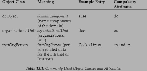
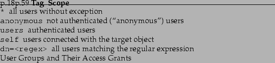
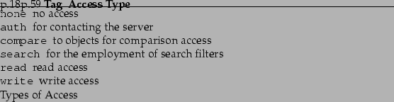
![\includegraphics[width=.75\linewidth]{ldap_y2_clconf}](img45.png)
![\includegraphics[width=.75\linewidth]{ldap_y2_adconf}](img46.png)
![\includegraphics[width=.75\linewidth]{ldap_y2_modconf1}](img47.png)
![\includegraphics[width=.75\linewidth]{ldap_y2_modconf2}](img48.png)
![\includegraphics[width=.75\linewidth]{ldap_y2_modconf3}](img49.png)
![\includegraphics[width=.75\linewidth]{ldap_y2_objtemp}](img50.png)
![\includegraphics[width=.75\linewidth]{ldap_y2_usergr}](img51.png)
![\includegraphics[width=.75\linewidth]{ldap_y2_adset}](img52.png)
![\includegraphics[width=.75\linewidth]{yast2_inst_nisserver1}](img53.png)
![\includegraphics[width=.75\linewidth]{yast2_inst_nisserver2}](img54.png)
![\includegraphics[width=.75\linewidth]{yast2_inst_nisserver3}](img55.png)
![\includegraphics[width=.75\linewidth]{yast2_inst_nisclient}](img56.png)
![\includegraphics[width=.75\linewidth]{yast2_nfsclient}](img57.png)
![\includegraphics[width=.75\linewidth]{yast2_inst_nfsserver1}](img58.png)
![\includegraphics[width=.75\linewidth]{yast2_inst_nfsserver2}](img59.png)